Direction Gyro and Compass
Introduction
The direction gyro is used navigation, providing a stable heading reference when the aircraft is turning. This gyro is kept aligned to magnetic north through the use of a remote compass, located in the wing, which gradually aligns the direction gyro whenever the aircraft is not turning.
Components
Direction Gyro
This is a horizontal gyro, suspended tangent to the ground. In addition to the yaw axis the gyro can freely rotate along the pitch axis to remain tangent to the ground. This allows the direction gyro to keep a fixed heading in space.
The direction gyro drives the indications on the radio compass card:

and the heading indicator needle:

While the direction gyro can keep a fixed heading in space for short periods of time, over long time periods it is subject to different forms of drift. Below are the different forms of drift and their sources.
| Drift | Description | Northern Hemisphere Drift | Southern Hemisphere Drift |
|---|---|---|---|
| Earth | As the earth rotates depending on the latitude (north/south) the apparent direction of gyro drifts. This can be more clearly understood by considering a gyro very close to the north pole, the gyro remains pointed at a fixed angle in space irrespective of the earth rotation, as such the apparent direction drifts as the earth rotates. | increasing | decreasing |
| Latitude Nut | The earth rate drift can be effectively countered by an offset weight on the gyro, known as the latitude nut. This direction gyro does not have a latitude nut but instead is electronically corrected using the latitude knob allowing the pilot to adjust the latitude to keep the gyro accurate. | decreasing | increasing |
| Transport Wander | Similar to drift caused by the rotation of the earth, the aircraft can itself increase or decrease the rotation around the earth by flying east or west. Unlike drift from the earth's rotation there is no compensation for this error. | increasing (east) / decreasing (west) | decreasing (east) / increasing (west) |
| Random Wander | Due to imprecision in components and friction the gyro naturally precesses leading to an error of 1-3° per hour, there is also no way to correct for this drift. | random | random |
Slaving
Notably transport wander and random wander cannot be corrected. For this reason the direction gyro is used in conjunction with the remote compass so that each system can cover the other's weakness. The remote compass which is accurate on average over long timescales can be used to adjust the direction gyro back towards magnetic north an electric motor is used to precess the gyro towards the measured magnetic north. This is known as slaving the direction gyro to the magnetic compass. The modes are described below.
| Mode | Description | Slaving Rate |
|---|---|---|
| Direction Indicator | Decouples Direction Gyro from magnetic compass, resulting in no correction. | none |
| Slaving | Slowly slaves the Direction Gyro towards the magnetic compass when the aircraft has not been turning for at least 15 seconds. | 1°/minute |
| Fast-Slaving | Quickly slaves the Direction Gyro towards the magnetic compass when the aircraft has not been turning for at least 15 seconds. | up to 360°/minute |
Upon powering on or after the function selector switch is switched from DG to MAG the direction gyro enters fast slaving mode.
Warning
If fast-slaving is used when the aircraft is accelerating, turning or pitch attitudes beyond ±30° the direction gyro is slaved towards an erroneous magnetic compass heading.
Leveling
As the aircraft moves the gyro gradually topples, because it is pointed at a fixed point in space, leading to erroneous readings. Electrolytic switches are used to indicate when the gyro is out of level from gravity and a motor is used to precess the gyro back into the plane tangent to the ground.
Thermal Relay
A thermal relay is incorporated into the slaving circuit to control the fast-slave cycle. When the system is switched to the MAG position, the relay heats and closes after a brief delay, supplying high voltage to the slaving torque motor for rapid alignment of the gyro to magnetic north. After the fast-slave period ends, the relay cools and reopens, returning the system to its normal slaving rate. Because the relay must cool fully before another fast-slave cycle can occur, repeated switching between MAG and DG without sufficient cooling time can prevent proper slaving and result in heading errors.
Remote Compass Transmitter (J-4 Compass)
The remote compass is a magnetic field sensing device which detects the current magnetic north relative to the aircraft heading. As described above, this signal give an accurate indication of magnetic north on average, and thus can be used to slowly adjust (slave) the direction gyro towards magnetic north if it has incurred any errors.
The remote compass is pendulously suspended in fluid to damp excess movement. The remote compass pendulum is limited to 30° max angle in any direction. The result is that under normal operation the pendulum finds the level and give an accurate indication of the magnetic north.
Under turning, acceleration or pitch attitudes exceeding ±30° the pendulum is displaced from the correct value leading to erroneous heading indications for magnetic north. These errors can be observed by looking at the annunciator window to see how the measured error swings as the aircraft maneuvers.
Controls
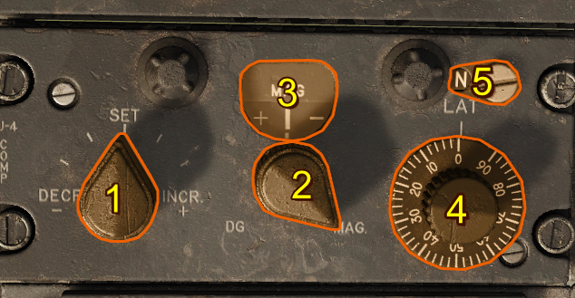
- Synchronizer Control Knob
- Function Selector Switch
- Annunciator
- Latitude Correction Knob
- Hemisphere Switch
Synchronizer Control Knob
The synchronizer control knob is used to manually rotate the direction gyro during slaved or non-slaved operation for rapid orientation of the heading system.
Function Selector Switch
The function selector switch is a two-position switch marked MAG and DG. When the switch is in the MAG position, the signals from the remote compass transmitter are being used and the system functions as a slaved heading system. When the switch is in the DG position, the system is operated in non-slaved mode. Automatic fast slaving occurs for approximately 15 seconds after power is initially applied or whenever the function selector switch is moved from the MAG to DG and then back to the MAG position.
Note
Straight and level flight must be maintained for 15 seconds before attempting to fast-slave the compass indicator. This should permit the rate-switching gyro to restore the magnetic slaving signal to the compass system and allow the compass indicator to synchronize with the correct magnetic heading.
Caution
Two minutes must elapse when switching from the magnetic mode to the directional gyro mode and back to the magnetic mode. This allows the thermal relay that controls the fast-slave cycle to cool. If the relay is not cooled properly, the indicator can stop at an erroneous reading.
Annunciator
The annunciator indicates the error between the direction gyro and the current sensed magnetic north, the synchronizer control knob can be used for rapid alignment of the heading pointer during slaved operation.
Note
During turns or while accelerating the indication might be erroneous.
Latitude Correction Knob
The latitude correction knob provides a manual latitude input to the gyro system to counteract apparent drift due to the earth's rotation rate. This should be set to the aircraft’s approximate latitude.
Hemisphere Switch
The hemisphere switch is set by the ground crew and is not accessible to the pilot.
Normal Operation
- Confirm the hemisphere switch has been properly set by ground crew before flight.
- Turn the function selector switch to the MAG position for normal, slaved operation.
- Maintain straight and level flight for at least 15 seconds to allow the remote compass transmitter and gyro to stabilize.
- If the heading indication is incorrect, rotate the synchronizer switch in the direction indicated by the annunciator until the heading pointer aligns with the magnetic heading.
- Adjust the latitude correction knob to the aircraft's current latitude to minimize direction gyro drift.
- If switching between MAG and DG wait 2 minutes before returning the switch to MAG to ensure the thermal relay cools, and the fast-slave cycle completes correctly.