Instrument Panel
The instrument panel of the F-100D contains a careful selection of essential gauges for basic operation, navigation, and system monitoring. All gauges suffer from installation error and other errors as a result of wear and tear. During the F-100D's service lifetime, it was common to leave a majority of the aircraft's gauges unmaintained. You might notice occasional frictional spikes and slight reading errors modeled by the simulation.
This section covers flight instruments needed for basic aircraft operation. For more information, see the respective system's section.
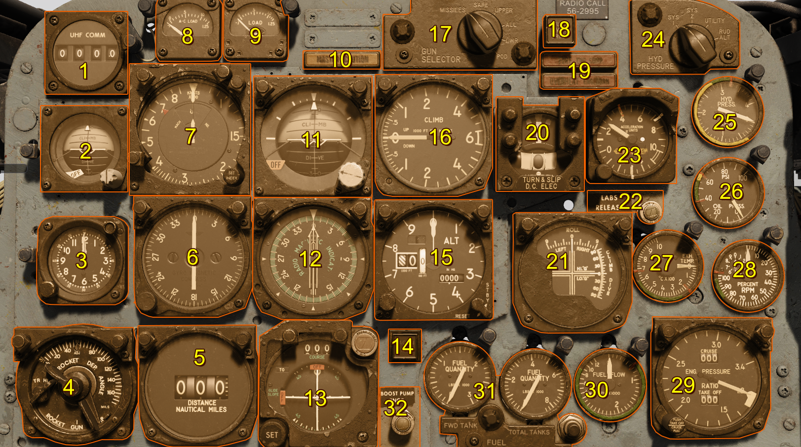
- Command Radio Remote Channel Indicator
- Standby Attitude Indicator
- Clock
- Sight Selector Unit
- Tacan Range Indicator
- Master Heading Indicator
- Airspeed and Mach Indicator
- AC Load Meter
- DC Load Meter
- Master Caution Light
- Attitude Indicator
- Radio Magnetic Indicator
- Course Indicator
- Tacan ILS Light (Inoperative)
- Altimeter
- Vertical Velocity Indicator
- Gun Missile Switch
- Attitude Indicator Fast Erection Button
- Fire and Overheat Warning Lights
- Turn and Slip Indicator
- LABS Dive and Roll Indicator
- LABS Release Indicator Light
- Accelerometer
- Hydraulic Pressure Gauge Selector Switch
- Hydraulic Pressure Gauge
- Oil Pressure Gauge
- Exhaust Temperature Gauge
- Tachometer (RPM)
- Engine Pressure Ratio Gauge
- Fuel Flow Indicator
- Fuel Quantity Gauges
- Fuel BOOST PUMP INOP Light
Caution
If you enable the custom dashboard layout in the F-100D Special Options, you can randomize the instrument panel layout each flight, or select one of your preference using the Grinelli Designs F-100D Dash Creator and entering the code into the menu.
Airspeed and Mach Indicator
The aircraft's air data computer (ADC) computes velocity based on temperature and pressure signals received by the pitot-static system. Specifically, it takes the difference between measured total and static pressure to compute dynamic pressure. Loss of either the pitot tube or static ports creates inaccurate readings.
The airspeed indicator also introduces installation and position errors up to 10 knots.
The Mach number is computed in the same manner, displaying aircraft velocity as a multiple of the speed of sound at local pressure altitude.
These two readings are displayed as a combined Airspeed and Mach indicator. The inner reading displays the airspeed in knots, and the outer reading displays the Mach number. The plot can set an index marker via a push-and-rotate actuation of the instrument's knob.
Attitude Indicator
Driven by an electric motor, a double mounted gyro maintains its vertical upright alignment while the aircraft maneuvers, displaying its attitude. This indicator is subject to precession errors, but re-aligns itself with a self-erecting mechanism.
A knob provides reference adjustment up and down to align it with the displayed artificial horizon.
Turn and Slip Indicator
The turn and slip indicator provides turn direction and rate information on a vertical needle. A standard 4 minute instrument turn places the vertical turn needle over the corresponding direction's hash mark.
The slip indicator displays horizontal accelerations in the lateral plane with a slip ball. For coordinated turns, use a combination of rudder input and the aircraft's yaw damper to center the slip ball.
Accelerometer
The accelerometer measures the aircraft's G load in the normal axis. The accelerometer has 3 needles:
- Maximum positive G load
- Maximum negative G load
- Current G load
A push-to-reset knob zeroes the maximum and minimum G load needles.
Altimeter
The altimeter displays the static system's current reading corrected for non standard temperature set by the pilot via a rotate actuation on instrument's pressure setting knob. Current pressure setting is displayed in the Kollsman's window, and is usually set to the local sea-level pressure in inches of mercury. Correct application of local sea-level pressure setting displays the aircraft's mean-sea-level altitude on the altimeter.
The altimeter can operate in two modes: servoed and standby. - In standby mode, the altimeter acts as a normal pressure based altimeter with any static port errors. - In servoed mode, the altimeter instead displays the corrected values from the air data computer.
To set the altimeter into servoed mode, hold the reset switch on the face of the altimeter to the reset position until the standby flag clears.
Vertical Velocity Indicator
The vertical velocity indicator computes the aircraft's vertical velocity from static pressure signals from the ADC, displaying the result in feet per minute. Lag is an inherent consequence of the design of the indicator, so readings delayed up to 6 seconds with substantial positional and gauge installation errors.
Clock
The ABU-11 clock has two ways of keeping time:
- On the clock face, you have two hands that work as a regular 12 hour clock with no AM or PM setting. The dial at the bottom-left of the instrument adjusts the time.
- Another second set of hands act as a stopwatch showing you seconds and minutes. The button at the top-right of the instrument cycles the stopwatch to START, STOP, and RESET.
Standby Attitude Indicator
The standby attitude indicator provides redundant function to the Attitude Indicator. The systems functions identically (including adjustment), but operate on independent gyros.
Attitude Indicator Fast Erection Button
This button is marked "PUSH VGI ERECT", and permits fast erection of the attitude gyros when pressed. Keep the button pressed for a duration proportional to the amount of suspected gyro misalignment.
Caution
To avoid creating additional misalignment errors, press the button in level flight at constant speed.