A-4 Gunsight

Introduction
The A-4 Gunsight is a lead computing optical sight. This system has a gyro to assist in computing the lead solution for aerial gunnery. Its primary input is the range, which can be achieved either from the onboard APG-30 radar system, or manually by the pilot using the optical sight to range.
The system can also be used for ground attack using either a fixed sight where pre-calculated depression tables, or the inbuilt automatic bombing mode.
Controls
Mechanical Cage Lever
The mechanical cage lever cages the sight to the boresight. With the sight mechanically caged, the reticle is fixed, and its sizee size is determined by the wingspan lever.
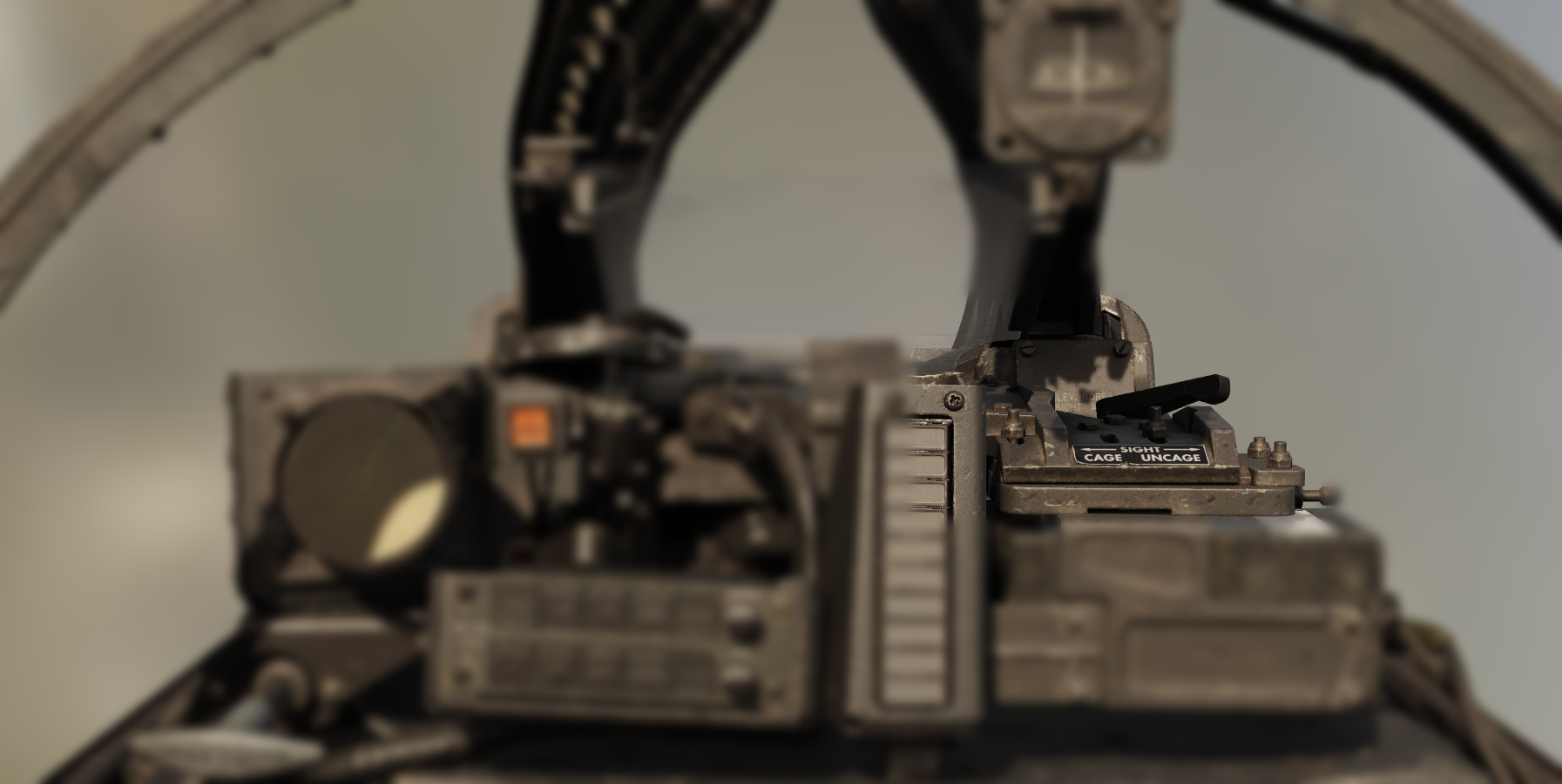
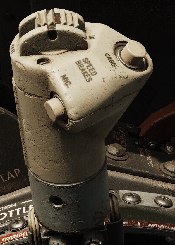
Electrical Cage Button
Pressing the electrical cage button stabilizes the reticle by providing the fire control system a range of 850 feet. The rigidity of the sight is increased to reduce reticle movement during hard maneuvering.
If this button is depressed, the Sight Selector Switch automatically moves to the gun position.
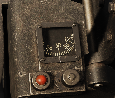
Range Dial
The range dial indicates the current target range in feet being used by the sight.
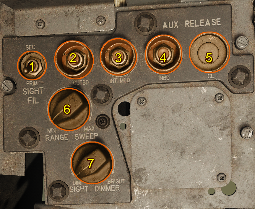
Radar Range Sweep Knob
The Range Sweep Knob (dial 6 below) is found next to the Auxiliary Release Buttons, and reduces the maximum lock-on distance for the radar, preventing the radar from locking onto undesirable objects such as the ground or ground objects. During normal operation at altitudes 6,000 feet or higher above ground level, the rheostat should be at MAX.
| Range Limit | Setting (feet) |
|---|---|
| MIN | 3,000 |
| MAX | 9,000 |
The value changes linearly between the min and max settings.
Sight Dimmer
The brightness of the reticle can be adjusted using the Sight Dimmer rheostat (dial 7 below).
Sight Filament Selector Switch
The primary or secondary filament in the dual-filament sight reticle bulb powered by the secondary bus and the tertiary bus. Select the filmane using the filament selector switch (dial 1 below). If the primary filament fails, set the switch to the SECONDARY position.
Manual Ranging Control (Throttle)
for automatic radar ranging, the throttle grip is normally in the full counter-clockwise position. Twisting the throttle grip clockwise decreases range from 2,700–12,000 feet.
Rotating the throttle full counter-clockwise returns ranging to automatic operation.
Wingspan Lever
The wingspan lever changes the size of the reticle, matching the angular size of a target at the indicated range. Setting the target's wingpan can confirm the radar ranging is correct, or assist manual ranging, visually matching the reticle width with the target's wingspan.
A mechanical linkage connects the interactive wingspan lever with the actual wingspan lever of the A-4 sight.

Radar Lock-On Light
When the radar range gate has achieved lock-on, the lock light illuminates.

Radar Reject Button
The radar reject button is located on the flight stick. Cancel radar locks by pressing the Radar Reject Button (for example, if the current range is much lower or higher than the desired target range). The radar continues to increase scan range until it finds a target or reaches max range, at which time it begins a new scan at minimum range.
Pressing the radar reject button also sets the Sight Selector Switch to the GUN position.
Sight Selector
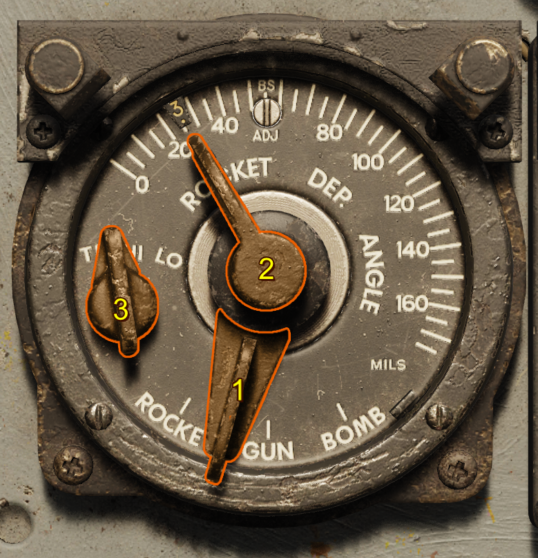
1. Sight Selector Switch
There are three options rocket, gun, bomb.
| Selection | Range (feet) | Electrically Caged |
|---|---|---|
| GUN | Range from radar or manual | Free to move unless electrical cage is depressed |
| ROCKET | 850 (fixed) | Caged to ECSL + Depression Angle |
| BOMB | 850 (fixed) | Caged to ECSL + 10° (used with [automatic bombing mode])(#bomb-air-to-ground-automatic) |
Caution
If the radar reject button is depressed, this switch automatically moves to the GUN position.
2. Sight Depression
This sets the depression from the boresight in mils when either in the rocket or bomb mode.
3. Target Speed Switch
This switch sets the effective velocity of the own aircraft and the closure rate for the sight calculations. Each setting is phrased in terms of the target velocity.
| Selection | Own Speed (knots) | Target Speed (knots) | Closure Rate (knots) |
|---|---|---|---|
| TR | 300 | 200 | 100 |
| HI | 600 | 500 | 100 |
| LO | 600 | 200 | 400 |
Operation
The A-4 gunsight can be used in air-to-air or air-to-ground operation. The sight selector selects each modes of operation as described below.
If the sight select mode is in manual, the armament mode is in bombs or napalm, and the bomb-arm switch is in SAFE, the gunsight pipper extinguishes, indicating a dud would be dropped off the aircraft.
Gun (Air-to-Air)
With the sight selector in the GUN position and the sight mechanically uncaged, the rate gyro inside the sight controls the pipper location to provide a gunnery solution based on the set range. The target speed switch should be set on the closest target speed:
| Selection | Description |
|---|---|
| HI | High Speed Targets |
| LO | Low Speed Targets |
| TR | Tracking Shots (at similar speeds to the target) |
Ranging
The range is controlled automatically by the radar, or manually using the throttle twist.
The radar automatically locks onto any sufficiently strong reflections, including the ground. The range is indicated on the range dial. If the range doesn't match the desired target, the target can be rejected using the radar reject button, initiating a new scan starting at the minimum range. If no targets are found by the time the scan reaches its maximum range, the scan begins again at the minimum range.
Range is validated by using the wingspan lever to set the wingspan of the current target on the gunsight. Then, the target is at the correct range when the wingspan matches inside of the reticle's tick marks.
Gunnery
The sight must be allowed to stabilize, attaining a correct solution for the current attack geometry. Keeping the reticle on the target for 1-2 seconds before firing.
Rocket (Air-to-Ground Manual)
With the sight selector in the ROCKET position and the sight mechanically uncaged, the Sight Depression controls the depression (in mils) of the reticle from the electrically caged sight line.
In this mode, the sight can be used in this for manual bombing or rocket attacks.
Bomb (Air-to-Ground Automatic)
The A-4 sight can use the inbuilt gyroscope to calculate target position. By using information such as airspeed to calculate bomb trajectory, an inbuilt mechanical computer determines when bomb trajectory coincides with the target position, and sense the bomb release signal once a solution is found.
The bombsight works on the principle that the line of sight rate corresponds to the slant range to the target. To facilitate this the reticle is automatically depressed 10° in the bomb mode. Keep the reticle on the target and allow the system to measure the line of sight rate. Once parameters are met, the reticle extinguishes and the bomb is released.
To protect the gyros, the electrical cage must be held up until the target is in the sight. Then, smoothly follow the target under the pipper to get an accurate measurement. Jerks or bumps can cause bombs to release prematurely.
Sight Lines Definitions
Fuselage Reference Line (FRL)
The defined reference line for pitch for the aircraft. Every other line is referenced from this line.
Mean Fixed Bore Line (MFBL)
The mean fixed bore line is a line drawn from the average position of the gun muzzles drawn parallel to the average boresight of the guns.

True 0 Prediction Sight Line (T0PSL)
The line drawn from the A-4 sight position parallel to the Mean Fixed Bore Line.
0 Prediction Sight Line (0PSL)
A line depressed by some angle from the True 0 Prediction Sight Line to harmonize this line and the Mean Fixed Bore Line at some distance (usually 2,000 feet).
Electrically Caged Sight Line (ECSL)
A line depressed by 1.1 mils from the 0 Predication Sight Line to account for bullet drop at approximately 850 feet.
This sight line is what is used when the sight is electrically or mechanically caged.