Hydraulic System
Introduction
The aircraft has three separate constant-pressure type hydraulic systems: utility, and two flight control systems. Each system is individually pressurized by a engine-driven hydraulic pump to 3,000 psi.
In the event of engine-driven pump failure, the secondary flight control system can be driven by a deployable Ram Air Turbine (RAT).
Utility System
This system has a 2.7-gallon reservoir pressurized by an engine pump. It supplies hydraulic power to the following:
- Rudder
- Landing gear and doors
- Wheel brakes
- Wing flaps
- Nose wheel steering
- Speed brake
- Automatic Flight Control System (AFCS)
- Gun and purge Door
- Ram Air Turbine Door
If system 1 pressure is too low to power the rudder, an automatic valve powers the rudder from the number 2 flight control system.
Emergency Flap Accumulator
If the utility hydraulic system or flap control fails, flaps can be lowered for landing using the emergency flap switch.
Warning
The Emergency Flap Accumulator has sufficient stored energy to lower the flaps only once.
Emergency Nose Wheel Accumulator
If the utility hydraulic system fails, the emergency gear release can drop the main gear by gravity. On its own, the nose gear cannot be dropped by gravity, so an emergency accumulator is provided to drop the nose gear.
Flight Controls 1 & 2 Systems
Two independent and simultaneously operating hydraulic systems (1 and 2) actuate the primary flight control surfaces. Each systems is powered by its own engine pump, supplying half the power demand of control surfaces.
Failure of one systems doesn't affect the other. In the event of a frozen engine or engine pump failure, the number 2 hydraulic pressure can be maintained by a deploying the Ram Air Turbine.
In the event of utility system failure, the number 2 system also provides power to the rudder.
The following items are powered by these systems:
| Item | Hydraulic System |
|---|---|
| Ailerons | 1 & 2 |
| Horizontal Stabilizer | 1 & 2 |
| Horizontal Stabilizer Trim | 2 |
| Rudder (in case of utility failure) | 2 |
Ram Air Turbine (RAT)
This acts as an emergency hydraulic pump for the number 2 system. If engine RPM drops below 40%, the centrifugal switch triggers the RAT deployment automatically, unless there is weight on the nose gear's wheel. The RAT can also be deployed manually using the lever.
If the RAT door is open, an audible warning tone plays in the headset, and the landing gear handle knob light illuminates.
If the pump is no longer needed, it must be shut down manually using the lever in the cockpit.
Utility hydraulic pressure is required to open the RAT, but in the event of of utility hydraulic failure, stored energy in the Ram Air Turbine door emergency accumulator is used.
You can test deployment of the Ram Air Turbine in flight with the flight control hydraulic system test switch.
Emergency Wheel Brake Pump
In the event of utility hydraulic pressure loss, an electrically-driven pump pressurizes wheel brake accumulators if the pressure drops below 750 psi. When the aircraft is cold and dark, if you depress the wheel brake, the pump can be checked for correct function by listening for its sound.
Controls and Indicators
Hydraulic Pressure Indicator and Knob
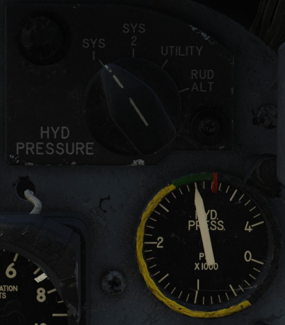
This knob and gauge indicate the pressure of the selected system.
Ram Air Turbine Door Lever
Deploys the Ram Air Turbine manually, and automatically actuates if it deploys automatically.
Flight Control Hydraulic System Test Switch
Holding this switch at the SYS 2 OFF position closes the test valve ,removing hydraulic pressure for this system. Moving the switch to RAM TURB ON SYS 2 OFF removes hydraulic pressure from the number 2 system, and provide utility hydraulic power to the Ram Air Turbine, and opens the ram air turbine door lever.
After testing the lever, close the Ram Air Turbine Doors by moving the lever to the aft position.
Note
A nose gear load switch prevents the number 2 system from being shut off on the ground.
Caution
Since this test is to be carried out during flight: a pressure switch prevents the test valve from being actuated if the number 1 system pressure is lower than 650 psi, avoiding primary flight control power loss.
Rudder Hydraulic Test Switch
This spring-loaded switch tests if the hydraulic summing valve is functioning correctly for the rudder actuator, ensuring that even in the event of insufficient utility pressure, the rudder functions using the number 2 system pressure.
Hold the switch in the ALTERNATE RUDDER position to shut off utility pressure, then the rudder can be moved. Confirm rudder pressure rises from nominal pressure up to 3,000 psi, matching the pressure of the number 2 hydraulic system.
Emergency Speed Brake Dump Lever
In the event of utility hydraulics failure with the speed brake in the open position, retract the speed brake. Without hydraulic pressure, this isn't possible. The dump lever releases any hydraulic pressure, allowing the speed brake to be retracted by airflow.
Emergency Gear Release
In the event of hydralic faailur, this lever deploys landing gear by gravity. Nose gear is deployed using hydraulic pressure stored in the emergency nose wheel accumulator.
Warning
After this system is used, the aircraft must be repaired in order to reset this system.
Emergency Flap Switch
In the event of electrical flap control failure or utility hydraulic failure, this switch deploys wing flaps to the DOWN position.
Warning
There emergency flap accumulator energy stores are only sufficient to lower the flaps once.