Lighting Control Panels
Exterior Lighting
A position light is on each wing tip, and two are in the trailing edge of the fuel vent outlet fairing above the rudder. The aircraft has two recognition lights, one on the upper fuselage and one on the lower fuselage. The aircraft also has two anti-collision or beacon lights, one on the upper fuselage and one on the lower fuselage.
The retractable landing-taxi lights are in the lower surface of the fuselage.The lights extend for use as landing lights until the weight of the aircraft is on the nose gear, then the lights extend farther to provide taxi lighting.
Some aircraft have a single floodlight in each wing. The lights face inboard and aft for illumination of the aft fuselage and empennage to facilitate visibility during night formation.
Controls
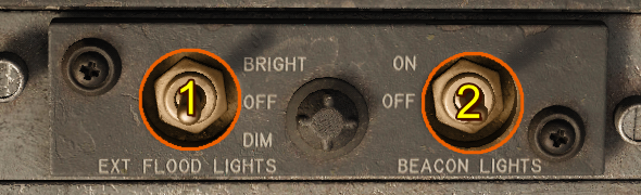
Exterior Flood Lights
The exterior flood lights controlled by this switch and can operate in bright, dim, or off. They are located on the top of the wing inboard of each wing fence illuminating aft.
Beacon Lights
This switch controls the beacon lights on the top and bottom of the fuselage and only operate in on or off.
Interior Lighting
Most instruments receive indirect lighting from individual fixtures of either the ring or the post type, while some instruments are integrally lighted. The position markings and names of the controls and switches on the consoles and instrument panel are lighted indirectly by edge lighting transmitted through the control panels. Direct lighting of the consoles and instrument panel is supplied by floodlights on the under surface of the instrument panel shroud and canopy sills. (The indirect lights and floodlights furnish conventional red light.)
Floodlighting can be reduced or completely closed off by turning a knob at the end of each lamp. The floodlights are adjustable, and can be directed toward any spot on the instrument panel. A thunderstorm light on each side of the cockpit provides intense white light to reduce the blinding effects of lightning.
A standard type G-4A utility light fits into a socket above the right console for general cockpit lighting. The utility light can be removed from its socket to light areas of the cockpit not normally lighted by other interior lights.
Controls
- Thunderstorm Lights Rheostat
- Instrument Lights Rheostat
- Console Lights Rheostat
- Position Lights Switch
- Position Lights Dimmer Switch
- Refueling Probe Light
- Indicator Light Test Switch
- Indicator Light Dimmer Switch
- Fuel Quantity and Magnetic Compass Light Switch
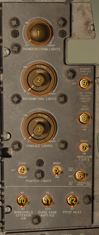
Thunderstorm Lights Rheostat
Controls two white thunderstorm lights powered by the primary bus.
Instrument Lights Rheostat
The outer position controls the flood light for the instrument panel. The inner position controls the indirect lights on the instruments themselves.
Console Lights Rheostat
The outer position controls the flood light for the side consoles. The inner position controls the console back lighting.
Position Lights Switch
This controls the illumination of the position and recognition lights. When flash is selected the position lights flash at a rate of 40 cycles per minute.
Position Lights Dimmer Switch
This controls the brilliance of the position and recognition lights.
Refueling Probe Light
Controls illumination of the refueling probe area. Used to assist in air refuelingoperations during low visibility conditions.
Indicator Light Test Switch
This switch can be used to test all indicator lights in the aircraft however when the switch is released from either position the dimming is reset to the bright position.
Indicator Light Dimmer Switch
This switch controls the dimming state for the indicator lights.
Fuel Quantity and Magnetic Compass Light Switch
Three position switch that illuminates the magnetic compass and the 335- or 450- gallon drop tank fuel quantity gauge.