Fuel System
Introduction
The fuel system includes three main tanks in the fuselage and a tank in each wing. Drop tanks can be installed on any of the six wing pylons.
A series of valves and float triggered pumps automatically balances fuel in the aircraft by. All fuel ends up in the forward fuselage tank where it is then passed to the engine through the manifold and a 1.6-gallon inverted flight tank which gives fuel for short periods of negative or zero g.
The aircraft has a single point pressure refueling system which allows for both ground and air-to-air refueling of all the aircraft's internal tanks. This system also has provisions for filling 275- and 335-gallon drop tanks on the intermediate pylons allowing for in-flight refueling on these tanks on intermediate pylons. Other tanks on other pylons cannot be refueled this way.
Fuel Tanks
There are 4 primary fuel tanks:
| Tank | Cells | Capacity (combined in lbs) | Description |
|---|---|---|---|
| Forward Fuselage | Upper, Centre Left, Centre Right, Lower | 2,912 | Engine Manifold primarily draws from this tank. |
| Intermediate Fuselage | Left, Right | 1,391 | These primarily feed into the forward fuselage however in case of transfer pump failure the right cell can directly feed the engine. |
| Aft Fuselage | Centre | 702 | This primarily feeds into the forward fuselage however in case of transfer pump failure the aft fuselage can gravity transfer to the intermediate fuselage tank. |
| Wing | Left, Right | 2,723 | These feed into forward fuselage by gravity and the scavenge pumps |
| External | Up to one per wing pylon | configuration dependent | These feed into the forward fuselage tank via bleed air pressure. Which pair of tanks feeding depends on the drop tank selector switch position. |
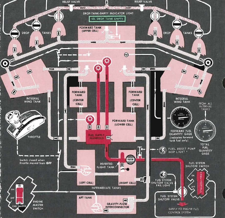
Inverted Flight Tank
The inverted flight tank is the direct feed to the engine. The inverted flight tank can be fed either from the manifold, which is inturn fed by the upper and lower forward fuselage tank, or the intermediate fuselage tank.
The geometry of this tank is designed such that when inverted there is still approximately 1.6 gallons of fuel for short periods of operation. The length of time of operation before flameout depends on the fuel flow as this directly impacts how quickly this inverted flight tank is exhausted.
The following table includes approximate values for afterburner and military thrust:
| Power Setting | Time Before Flameout (seconds) |
|---|---|
| Afterburner | 1.5 |
| Military | 6.0 |
Fuel Booster Pumps
There are a total of three boost pumps, all three are located in the forward tank. Two AC pumps are located in the upper cell and one DC pump is located in the lower cell. These all feed into the fuel supply manifold which can also be gravity fed from the lower forward tank cell.
Fuel Transfer (and Scavenge) Pumps
There are two transfer pumps. Normally the intermediate and aft tanks transfer to the forward tanks when the level of the forward tank drops. This is to maintain mass balance but also because the primary feed is in the forward tank.
In the event of transfer pump failure, it might not be possible to transfer all fuel from the intermediate and aft tanks as such the intermediate tank can directly feed the engine by gravity. The aft tank can also transfer using gravity to the intermediate tank for direct feed to the engine in this scenario.
Warning
When the afterburner is operating, fuel flow exceeds transfers from external and internal tanks to the forward tank. Monitor the forward fuel tank level and avoid engine flame-outs due to insufficient fuel.
Drop Tanks
Drop tanks can be mounted on any of the wing pylons. However only the 335- and 450-gallon tanks can be refueled when mounted on the intermediate pylons. The list of the available tanks is shown below.
| Tanks (gallon) | Pylons | Mid-Air Refuelable |
|---|---|---|
| 200 | All | No |
| 275 | Intermediate only | No |
| 335 | Intermediate only | Yes |
| 450 | Intermediate only | Yes |
Tanks are pressurized by the engine bleed air when drop tank selector switch is set to any position other than OFF. In the event of electrical failure the bleed air valves are normally open position allowing fuel transfer from all external tanks simultaneously.
Warning
When the afterburner is operating, fuel flow exceeds transfers from external and internal tanks to the forward tank. Monitor the forward fuel tank level and avoid engine flame-outs due to insufficient fuel.
Fuel System Shutoff Valve
The fuel shutoff valve is an electronically actuated valve which can be used to shut off fuel to the engine. In the event of valve failure the fuel system shutoff valve fail light illuminates.
Controls and Indicators
Drop Tank Selector Switch
This selects which external tanks are pressurized by the engine bleed air. In the event of electrical failure the bleed air valves are normally open position allowing fuel transfer from all external tanks simultaneously.
Drop Tank Empty Indicator Light
This indicates there is no longer any fuel pressure from the drop tanks. Because the external tank fuel line is shared with the internal wing tank scavenge pumps, this light extinguishes once the wing tanks begin to scavenge at approximately 4,000 pounds of fuel. This light illuminates again once wing tanks are empty (approximately 1,500 pounds of fuel remaining).
Fuel System Shutoff Valve Fail Light
This light illuminates if the fuel system shutoff valve is stuck as this could restrict fuel flow to the engine.
Air Refueling Switch
This de-energizes the transfer control valves for the internal wing and external fuel tanks, allowing the single point pressure refueling system to refuel these tanks correctly.
Warning
Do not position this to READY too soon as this prevents approximately 25 pounds per minute of fuel from being transferred from the internal wing tanks to the forward tank.
Air Refueling Indicator Light
This light simply indicates if the air refueling switch is in the ready position. It does not indicate if all the systems are functional.
Fuel Flow Indicator
The fuel flow indicator shows the rate of fuel flow from the fuel control unit to the engine in pounds per hour.
Warning
This gauge does not monitor fuel flow to the afterburner.
This gauge is powered by the 26 V AC instrument bus.
Fuel Boost Pump Light
This illuminates if fuel pressure to the engine is less than 5 psi, indicating a condition where one or more fuel boost pumps are non-functional.
Forward Fuel Quantity Gauge
Indicates total quantity of all forward fuselage tanks.
Total Fuel Quantity Gauge
Indicates total quantity of all internal tanks.