Weapon Release Circuitry
Basic Armament Control Circuitry
The basic armament control circuitry sends release signals to the pylons to release rockets, bombs and dispenser contents. It can receive bomb pulses from either the manual delivery mode, automatic sight release release cue, or Low Altitude Bombing System release cue.
When a bomb pulse is received from the Aircraft Weapons Release System it is up to the weapons selection circuitry forward the pulses to the correct pylons to release ordinance.
All stations with their Station Release Selection Switch armed will receive the forwarded bomb pulse. Any stations which have jettison selected instead will convert the bomb pulse to a jettison signal (if the ordnance can be jettisoned).
AN/AWE-1 Aircraft Weapons Release System (AWRS)
Introduction
When the AWRS is active, any bomb pulse from the bomb-button or Low Altitude Bombing System is passed to the AWRS to sequence pylons, quantities and timing of bomb or rocket releases.
Station Release Selection Switches
For the Aircraft Weapons Release System to function correctly, all Station Release Selection Switches for the desired weapon type should be moved into either the NORM or JETT position (depending if armed release or jettison is required).
Controls
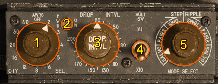
- Quantity Selector Switch
- Power Indicator Light
- Release Interval Switch
- Multiplier Switch (x10)
- Mode Select Switch
Quantity Selector Switch
With the Quantity Selector Switch in the OFF position electrical power is removed from the AWRS system and the Basic Armament Control Circuitry is used. With the Quantity Selector Switch set to any numbered position the AWRS is active and energized.
The selected number provides the AWRS with the quantity of release pulses in ripple modes.
See operation.
Release Interval Switch
The release interval switch sets the time interval in milliseconds (ms) between AWRS pulses.
Multiplier Switch (x10)
Setting the multiplier switch to x10 increases the release interval value by a multiple of 10. Setting it to x1 returns timing to the interval switch's value.
Modes
Operation
Release modes prouduce pulses distributed to pylons according to the release type. The following table describes how pulses are produced and forwarded to the release type circuitry after receiving each input signal from either the manual delivery mode or Low Altitude Bombing System release cue.
| Release Mode | Number of Pulses |
|---|---|
| STEP | Input signal produces only one pulse |
| RIPPLE | Input signal produces a sequence of pulses with intervals specified by the Release Interval Switch and Multiplier Switch. The sequence length is the setting on the Quantity Selector Switch provided the input signal is held on the entire duration of the sequence. If the input signal is released early (ie bomb-button released) the sequence immediately stops. |
There are 3 possible release types. Each type acts on sequence pulses.
| Release Type | Pulse Result |
|---|---|
| SINGLE | A single bomb is released from the next valid pylon in the release sequence if one exists. |
| PAIRS | A pair of bombs or rockets is released from the next valid pair of pylons in the sequence. |
| SALVO | Every valid selected pylon releases a bomb or rocket if the pylon is not empty. |
Examples
To assist in understanding the AWRS, below a few examples are shown. Each example assumes there are enough bombs on the plane in the correct configuration to drop the correct number of bombs or rockets.
| Release Mode | Release Type | Quantity Selector Switch | Interval (ms) | Multiplier Switch | Result |
|---|---|---|---|---|---|
| RIPPLE | SINGLE | 4 | 60 | x1 | 4 bombs is dropped with an interval of 60 ms between them. |
| RIPPLE | SINGLE | 6 | 100 | x10 | 6 bombs is dropped with an interval of 1000 ms (due to x10 switch) between them |
| RIPPLE | PAIRS | 3 | 150 | x1 | 3 pairs of bombs is dropped (total 6) with an interval of 150 ms between each pair. |
| RIPPLE | SALVO | 3 | 45 ms | x1 | For example, let's say the aircraft is armed with a 1, 1, 3, 3, 1, 1 MK-82 on each pylon. The first salvo drops 6 bombs, leaving 0, 0, 2, 2, 0, 0 on the aircraft. 45 ms later, 2 more bombss drop, leaving 0, 0, 1, 1, 0, 0. 45 ms later again, the remaining 2 bombs will drop, resulting in a total of 10 dropped bombs. |
Station Priority and Sequencing
Bombs or rockets drop in order of priority, alternating sides if two valid pylons share equal priority. The further a pylon is from the center, the higher its priority. The AWRS does not consider inactive pylons, empty pylons, nor pylons armed with an incorrect weapon type.
The following table displays each pylon's priority:
| Left Outer | Left Middle | Left Inner | Right Inner | Right Middle | Right Outer |
|---|---|---|---|---|---|
| 1 | 3 | 5 | 6 | 4 | 2 |
Note
Rockets/dispenser pods cannot send an empty signal. Once the outer rocket or dispenser pods are empty, the AWRS will not automatically step to the inner rocket or dispenser pods. Instead, it continues to assume they are valid. To use inner rocket or dispenser pods, use RIPPLE-STEP or RIPPLE-SALVO instead.
Warning
Station Release Selection Switches don't affect the AWRS pylon validity. These switches break the circuit between the AWRS and the pylon, causing the AWRS to get "stuck" if these pylons are set to OFF.