Indicator, Caution, and Warning Lights
Indicator, caution, and warning lights are placed throughout the cockpit in order to notify the pilot of the status of systems. Each category has a different meaning. Nearly all aircraft cockpit lights are powered by the primary bus.
| Category | Meaning | Color |
|---|---|---|
| Indicator | Safe operation status | Green |
| Caution | Possible need for corrective action, not time sensitive | Yellow |
| Warning | Requires immediate action, time sensitive | Red |
The three-position indicator light dimmer switch controls the brightness of the indicator, caution, and warning lights when the instrument panel lights are on. The in-flight control tester panel has its own integral brightness control.
Note
The indicator light test switch changes the indicator lights to bright when released. To dim the indicator lights after using the indicator light test switch, move the indicator light dimmer switch to BRIGHT, then DIM, and release to the center OFF position.
Indicator, Caution, and Warning Light Panel
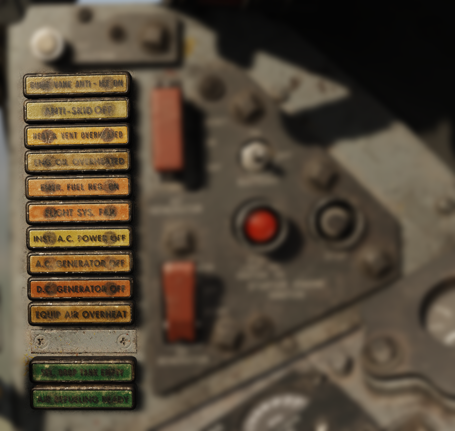
| Light | Category | Cause |
|---|---|---|
| GUIDE VANE ANTI-ICE ON | Caution | The ice detector unit in the engine guide vane has detected ice or the guide vane anti-ice switch is on |
| ANTI-SKID OFF | Caution | The anti-skid switch is off or the system has failed |
| HEAT & VENT OVERHEATED | Caution | |
| ENG OIL OVERHEATED | Caution | Engine oil temperature is higher than 127°C (260°F) |
| EMER FUEL REG ON | Caution | Fuel flow is being scheduled by the emergency fuel regulator |
| FLIGHT SYS FAIL | Caution | One or both flight control hydraulic systems have failed (system 1 or 2) |
| INST A.C. POWER OFF | Caution | AC Instrument Buses are not Receiving sufficient electrical power |
| A.C. GENERATOR OFF | Caution | AC generator is off the line |
| D.C. GENERATOR OFF | Caution | DC generator is off the line |
| EQUIP AIR OVERHEAT | Caution | The aft electronic equipment compartment has overheated\n Indicates possible failure of the equipment cooling or compartment turbine, failure of the turbine control system, or the ram air is not cooling the compartment |
| SEL. DROP TANK EMPTY | Indicator | selected drop tanks are empty |
| AIR REFUELING READY | Indicator | Air refueling switch is in the ready position, does not indicate that all components in the system are operational |
Indicator Light Test Circuit
The indicator light test circuit is a means of merely testing the integrity and operation of the bulbs. All indicator, caution, and warning lights illuminate simultaneously to exclude the engine compartment fire FIRE ENG COMP and overheat OVERHEAT ENG BURN warning lights, of which have a separate test circuit. All lights in the test circuit are powered by the primary bus.
Master Caution Light
The master caution light indicated certain indicator or caution lights have illuminated. The master caution light must be put out in order to not inhibit the illumination of additional lights. To extinguish the master caution light, the pilot must press the respective indicator or caution light that caused the master caution to become illuminated.
Note
Illumination of the following lights do not illuminate the master caution light:
- TRIMMED FOR TAKEOFF
- FIRE ENG COMP and OVERHEAT ENG BURN
- CANOPY NOT LOCKED
- SEL. DROP TANK EMPTY
- AIR REFUELING READY
- Ignition-on
- Landing gear warning light
Other
| Light | Category | Cause |
|---|---|---|
| CANOPY NOT LOCKED | Warning | The canopy is not fully closed and locked. |
| FIRE ENG COMP | Warning | An overheat or fire has been detected in the forward engine compartment or the fire system is being tested. |
| OVERHEAT ENG BURN | Warning | An overheat or fire has been detected in the aft engine compartment or the fire system is being tested. |
| TRIMMED FOR TAKEOFF | Indicator | The aircraft is trimmed for take off (260 KIAS condition). |